Home
/ 7 Pin Rv Trailer Connector Diagram - Diagram Curt 7 Way Rv Plug Wiring Diagram Full Version Hd Quality Wiring Diagram Tuataradiagram Romeorienteering It
7 Pin Rv Trailer Connector Diagram - Diagram Curt 7 Way Rv Plug Wiring Diagram Full Version Hd Quality Wiring Diagram Tuataradiagram Romeorienteering It
7 Pin Rv Trailer Connector Diagram - Diagram Curt 7 Way Rv Plug Wiring Diagram Full Version Hd Quality Wiring Diagram Tuataradiagram Romeorienteering It. Typically, there are 3 sorts of diagrams that individuals may look at when aiming to create cables for trailers. Wiring plug diagram created date: 7 way trailer wiring diagram is explained in details in the picture and the table below: Identified by key tab on outer ring between pin 3 and 4. The other has round pins.
7 way trailer wiring diagram is explained in details in the picture and the table below: Curt electrical connectors are designed and manufactured to give you a reliable connection every time you plug in your trailer. This wiring diagram for 7 pin trailer plug model is far more suitable for sophisticated trailers and rvs. White pin for the ground. Variety of 7 pin round trailer wiring diagram.
Trailer Wiring Basics For Towing Allpar Forums from www.allpar.com 7 way trailer wiring diagram is explained in details in the picture and the table below: Pictorial diagram of suggested wiring to pollak 7 pin socket. This connector is intended to be used for 12v abs and ebs on heavy duty trailers. If not, the arrangement will not function as it ought to be. 6 prong trailer wiring diagram is one of the most pics we discovered online from respectable sources. If your vehicle is not equipped with a working trailer wiring harness, there are a number of different solutions to provide the perfect fit for. It is often found on newer trucks and suvs that come equipped from the factory with a trailer hitch. Hi, i have a 2018 gmc denali and would like to know if anyone has a 7 blade trailer connector wiring diagram.
Wiring plug diagram created date:
7 way trailer wiring diagram is explained in details in the picture and the table below: White pin to your ground. Trailer side car side wiring plug diagram. Pictorial diagram of suggested wiring to pollak 7 pin socket. This wiring diagram for 7 pin trailer plug model is far more suitable for sophisticated trailers and rvs. Trailer wiring diagrams trailer wiring connectors various connectors are available from four to seven pins that allow for the transfer of power for the lighting as well as auxiliary functions such as an electric trailer brake controller, backup lights, or a 12v power supply for a winch or interior trailer lights. 6 prong trailer wiring diagram is one of the most pics we discovered online from respectable sources. Yellow pin for abandoned brake light and left turn markers. 7 pin trailer wiring found this in less than 20 seconds, obvious you didn't try very hard. 7 pin 'n' type trailer plug wiring diagram7 pin trailer wiring diagramthe 7 pin n type plug and socket is still the most common connector for towing. One has flat pins, which are often referred to as blades. Some of the wiring systems used for connecting a tow vehicle with a toad (or towed vehicle) are simpler than others, but there are standards for all of the connectors and how they are wired. White pin to your floor.
I'm making a 2' extension of a 7 blade male to a 7 blade female connector. This wiring diagram for 7 pin trailer plug model is far more suitable for sophisticated trailers and rvs. 7 pin trailer wiring found this in less than 20 seconds, obvious you didn't try very hard. 7 pin 'n' type trailer plug wiring diagram7 pin trailer wiring diagramthe 7 pin n type plug and socket is still the most common connector for towing. Typically, there are 3 sorts of diagrams that individuals may look at when aiming to create cables for trailers.
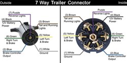
7 Way Rv Trailer Connector Wiring Diagram Etrailer Com from images.etrailer.com White pin to your ground. If your vehicle is not equipped with a working trailer wiring harness, there are a number of different solutions to provide the perfect fit for. The other has round pins. Each component ought to be set and connected with different parts in particular manner. White pin to your floor. Curt electrical connectors are designed and manufactured to give you a reliable connection every time you plug in your trailer. A wiring diagram is a simplified standard pictorial depiction of an electric circuit. 7 way plug wiring diagram standard wiring* post purpose wire color tm park light green (+) battery feed black rt right turn/brake light brown lt left turn/brake light red s trailer electric brakes blue gd ground white a accessory yellow this is the most common (standard) wiring scheme for rv plugs and the one used by major auto manufacturers today.
I'm making a 2' extension of a 7 blade male to a 7 blade female connector.
If not, the arrangement will not function as it ought to be. Some of the wiring systems used for connecting a tow vehicle with a toad (or towed vehicle) are simpler than others, but there are standards for all of the connectors and how they are wired. If your vehicle is not equipped with a working trailer wiring harness, there are a number of different solutions to provide the perfect fit for. The other has round pins. Typically, there are 3 sorts of diagrams that individuals may look at when aiming to create cables for trailers. 7 way trailer wiring diagram is explained in details in the picture and the table below: This car is designed not just to travel one place to another but also to carry heavy loads. Identified by key tab on outer ring between pin 3 and 4. One has flat pins, which are often referred to as blades. White pin to your ground. The round pin style is very rare. This wiring diagram for 7 pin trailer plug model is far more suitable for sophisticated trailers and rvs. This connector is intended to be used for 12v abs and ebs on heavy duty trailers.
Trailer wiring diagrams trailer wiring connectors various connectors are available from four to seven pins that allow for the transfer of power for the lighting as well as auxiliary functions such as an electric trailer brake controller, backup lights, or a 12v power supply for a winch or interior trailer lights. This connector is intended to be used for 12v abs and ebs on heavy duty trailers. Variety of 7 pin round trailer wiring diagram. I'm making a 2' extension of a 7 blade male to a 7 blade female connector. Curt electrical connectors are designed and manufactured to give you a reliable connection every time you plug in your trailer.
Trailer Wiring Connector Diagrams For 6 7 Conductor Plugs Trailer Wiring Diagram Diesel Trucks Trailer Light Wiring from i.pinimg.com White pin to your floor. 7 pin 'n' type trailer plug wiring diagram7 pin trailer wiring diagramthe 7 pin n type plug and socket is still the most common connector for towing. If your vehicle is not equipped with a working trailer wiring harness, there are a number of different solutions to provide the perfect fit for. It reveals the parts of the circuit as simplified forms, as well as the power and also signal links between the tools. I'm making a 2' extension of a 7 blade male to a 7 blade female connector. A wiring diagram is a simplified standard pictorial depiction of an electric circuit. Some of the wiring systems used for connecting a tow vehicle with a toad (or towed vehicle) are simpler than others, but there are standards for all of the connectors and how they are wired. They supply power to the taillights, turn signals, brake lights, trailer brakes, reverse lights, auxiliary power and include a ground connection.
The other has round pins.
White pin to your floor. One has flat pins, which are often referred to as blades. Trailer wiring diagrams trailer wiring connectors various connectors are available from four to seven pins that allow for the transfer of power for the lighting as well as auxiliary functions such as an electric trailer brake controller, backup lights, or a 12v power supply for a winch or interior trailer lights. This car is designed not just to travel one place to another but also to carry heavy loads. Typically, there are 3 sorts of diagrams that individuals may look at when aiming to create cables for trailers. In the trailer wiring diagram and connector application chart below, use the first 5 pins, and ignore the rest. The round pin style is very rare. Trailer side car side wiring plug diagram. 7 way plug wiring diagram standard wiring* post purpose wire color tm park light green (+) battery feed black rt right turn/brake light brown lt left turn/brake light red s trailer electric brakes blue gd ground white a accessory yellow this is the most common (standard) wiring scheme for rv plugs and the one used by major auto manufacturers today. It reveals the parts of the circuit as simplified forms, as well as the power and also signal links between the tools. Some of the wiring systems used for connecting a tow vehicle with a toad (or towed vehicle) are simpler than others, but there are standards for all of the connectors and how they are wired. 7 pin trailer wiring found this in less than 20 seconds, obvious you didn't try very hard. If not, the arrangement will not function as it ought to be.
Yellow pin for abandoned brake light and left turn markers 7 pin trailer connector diagram. 7 pin 'n' type trailer plug wiring diagram7 pin trailer wiring diagramthe 7 pin n type plug and socket is still the most common connector for towing.
Share :
Post a Comment
for "7 Pin Rv Trailer Connector Diagram - Diagram Curt 7 Way Rv Plug Wiring Diagram Full Version Hd Quality Wiring Diagram Tuataradiagram Romeorienteering It"


Post a Comment for "7 Pin Rv Trailer Connector Diagram - Diagram Curt 7 Way Rv Plug Wiring Diagram Full Version Hd Quality Wiring Diagram Tuataradiagram Romeorienteering It"